Group assignment 4:Embedded Programming
Compare the tools and processes used for various embedded architectures.
Understand the data sheets of microcontrollers.
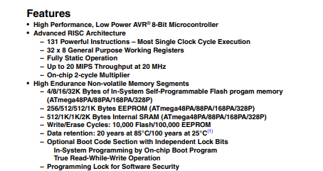
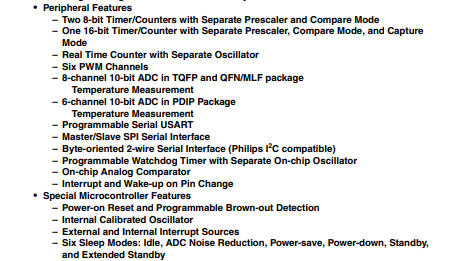
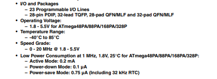
ATmega328P Datasheet
A datasheet is a complete technical document that provides detailed information about an electronic component. It explains how the device is designed, how it works, and how it should be used in a circuit.
The datasheet describes the internal structure, electrical characteristics, and operating conditions. It also gives a clear pin diagram and explains the function of each pin.
By reading the datasheet, we can understand how to properly connect and use the component in our project.
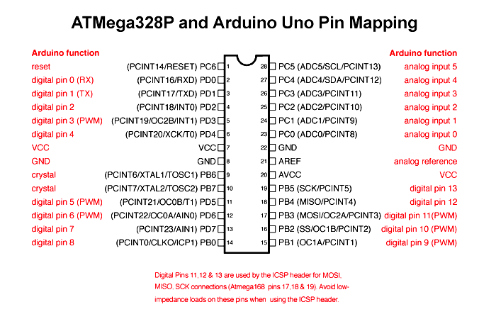
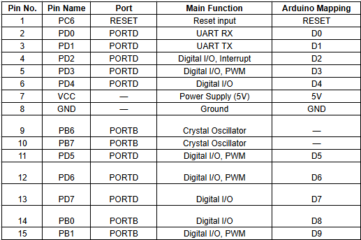
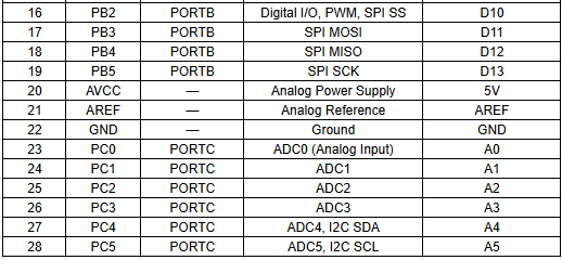
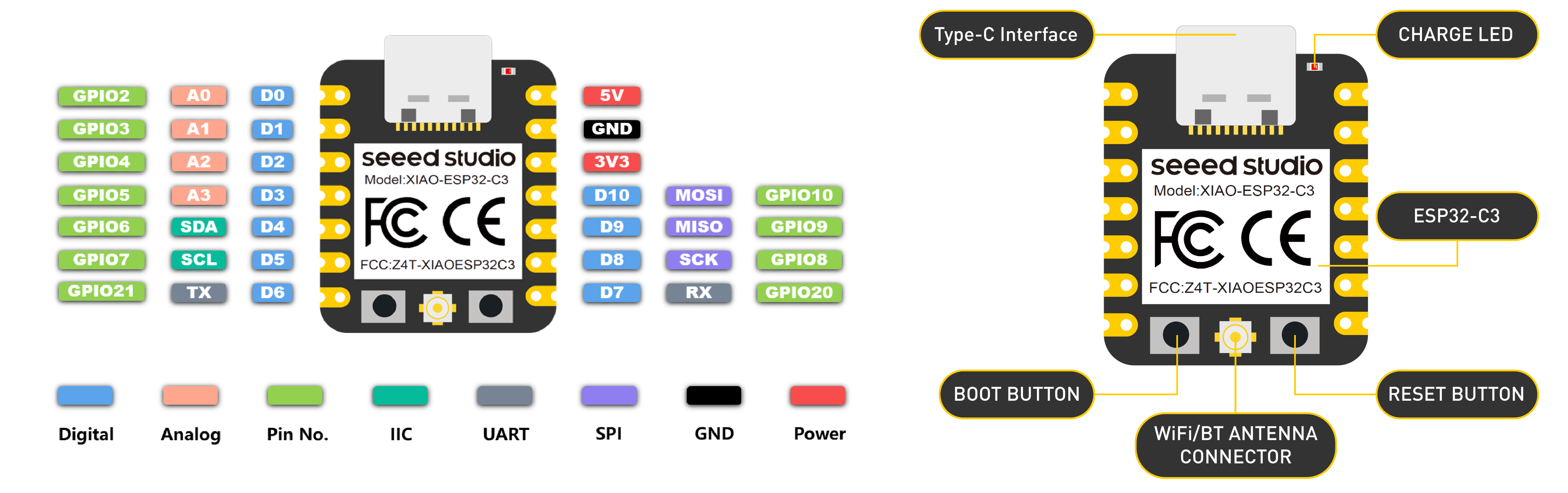
Pin Configuration :
In a microcontroller, there are many pins and each pin has a special function. Some pins are used as digital input and output,
while some are used for analog input to read sensor values. Certain pins support PWM to control things like LED brightness or motor speed.
Other pins are used for communication protocols such as SPI, I2C, or UART to connect with external devices.
Each pin has a specific role, which helps the microcontroller perform different tasks efficiently.
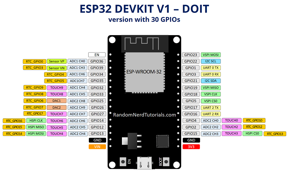
ESP32 Datasheet
ESP32 is a more advanced microcontroller board compared to Arduino Uno. It has built-in WiFi and Bluetooth,
so we can connect it directly to the internet or other wireless devices without using extra modules. It also has more processing speed, more memory, and more GPIO pins.
ESP32 supports advanced features like dual-core processing and multiple communication options. Because of these extra features, it is very useful for IoT and smart projects.
ESP32 Features
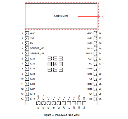
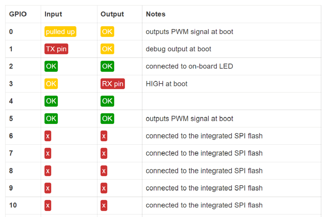
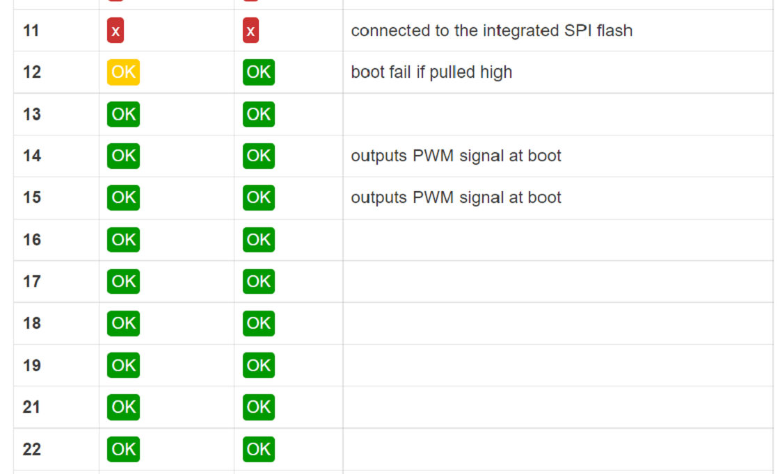
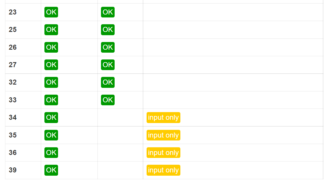
Pin Configuration :
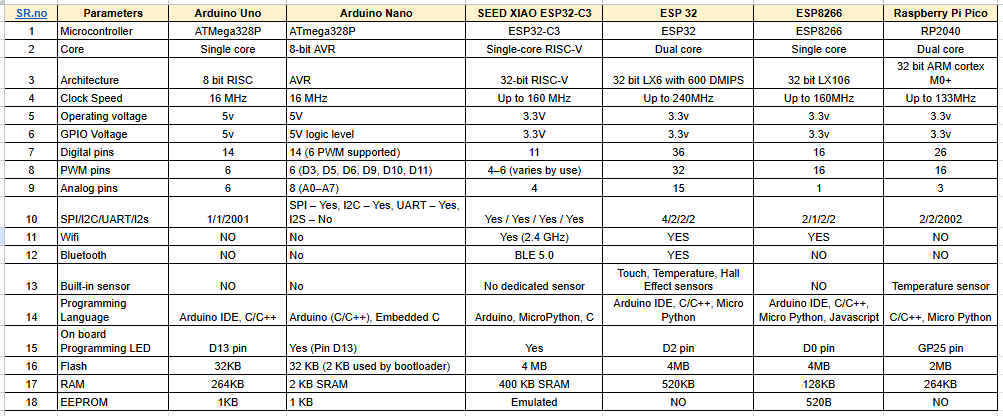
Comparison of Microcontrollers
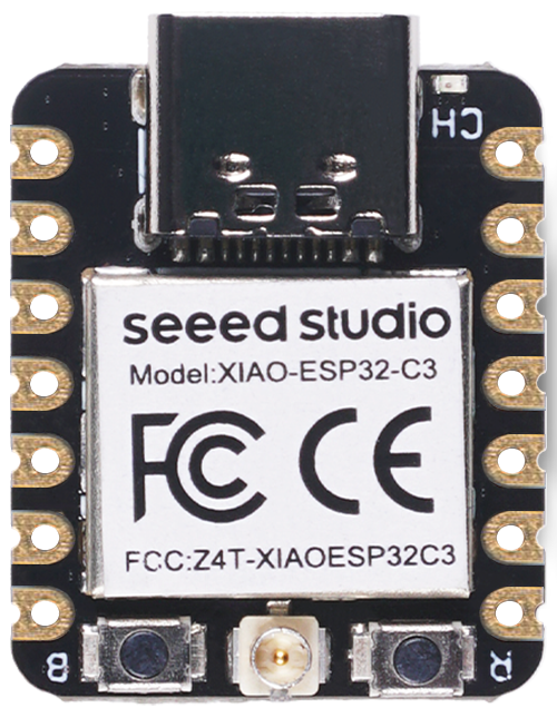
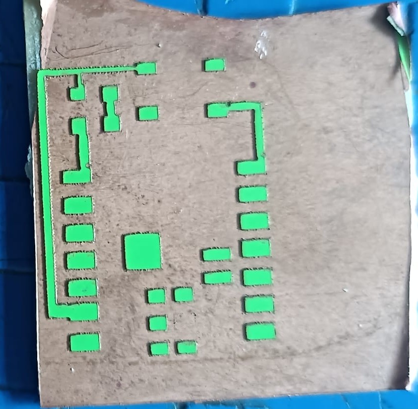
PCB for the XIAO ESP32-C3 :
this assignment, we worked as a group and designed a custom PCB for the XIAO ESP32-C3 module because it does not have an onboard LED.
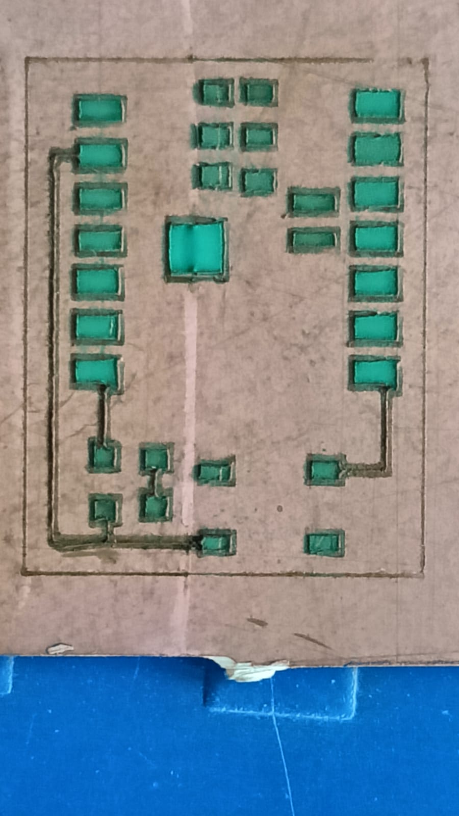
To test and practice programming easily, we decided to add an external LED on our own board. We fabricated the PCB using the etching process.
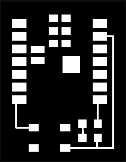
Step 1: In this week’s video lecture, Nils Gershenfeld explained different types of microcontroller boards and described their features and architecture.
During the lecture, he also showed PCB traces and how microcontroller boards are designed internally. From the lecture, we understood the PCB trace layout of the XIAO ESP32-C3 module. This helped us learn how to design and plan our own custom PCB board.
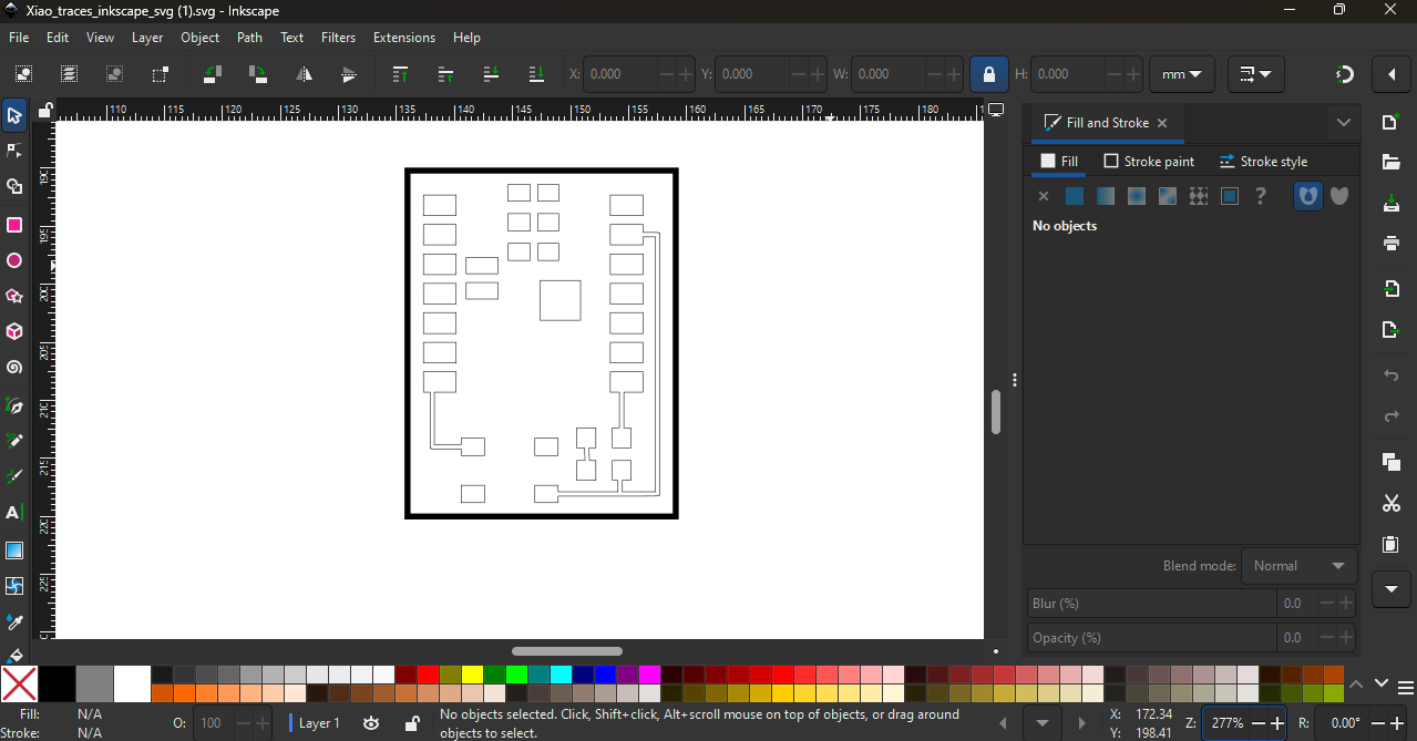
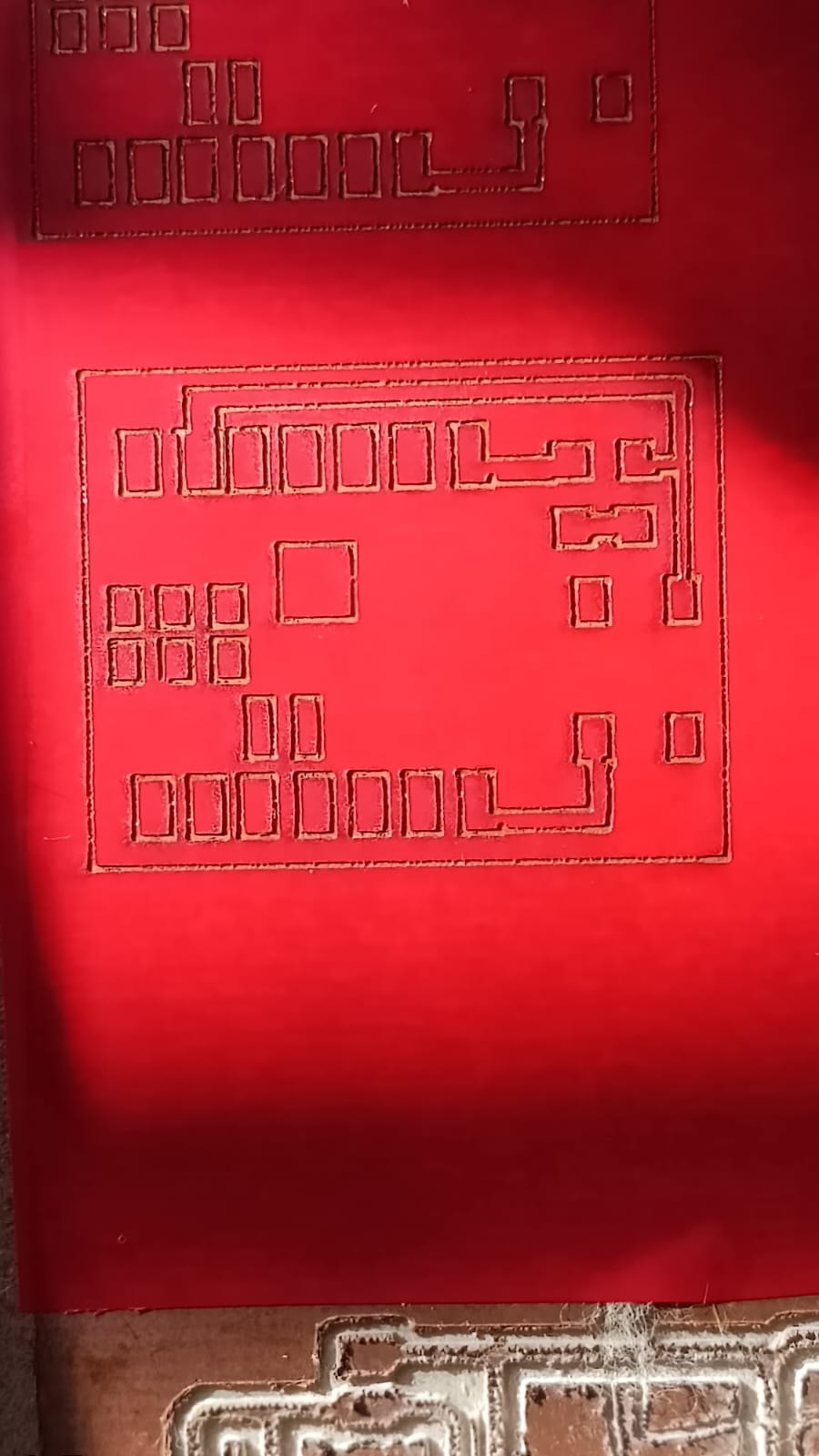
Step 2: Our plan was to use the laser machine during this process. So first, we converted the PCB trace image into vector format using Inkscape software.
Converting the image into vector format helped us prepare the design properly for laser cutting.
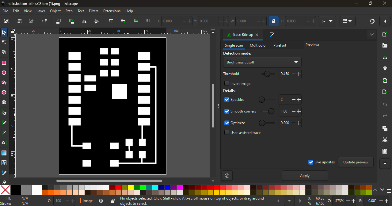
This step was important to make sure the traces were clean and accurate before moving to the next fabrication process.
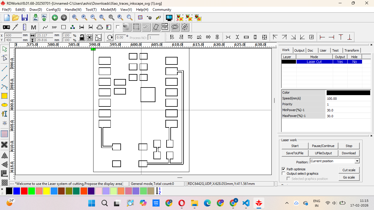
Step 3: After preparing the vector file, we imported it into RDWorks software and converted the design into a machine path for the laser cutter.
However, we were using an 80W CO₂ laser machine, which cannot directly engrave or cut metal surfaces. Since our PCB base was a copper plate, the laser could not engrave it directly.
So we tried different masking materials like paper tape, electrical tape, and vinyl paper to see which one would work properly for the process.
We tested the laser cutting process multiple times on different materials. We tried paper tape, electrical tape, and vinyl paper to check which material gave the best result.
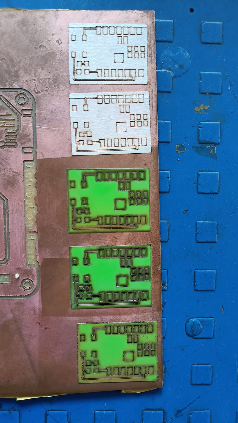
After testing different materials, we selected the best material for the cutting process.
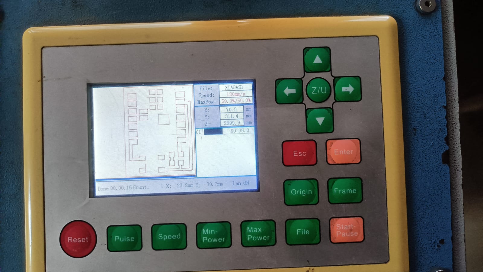
During this step, we made a small mistake — we forgot to invert (mirror) the PCB image before sending it to the laser machine.
Because of this, the first cut was incorrect. We understood the mistake, corrected the design by inverting the image, and then repeated the cutting process to get the final correct output.
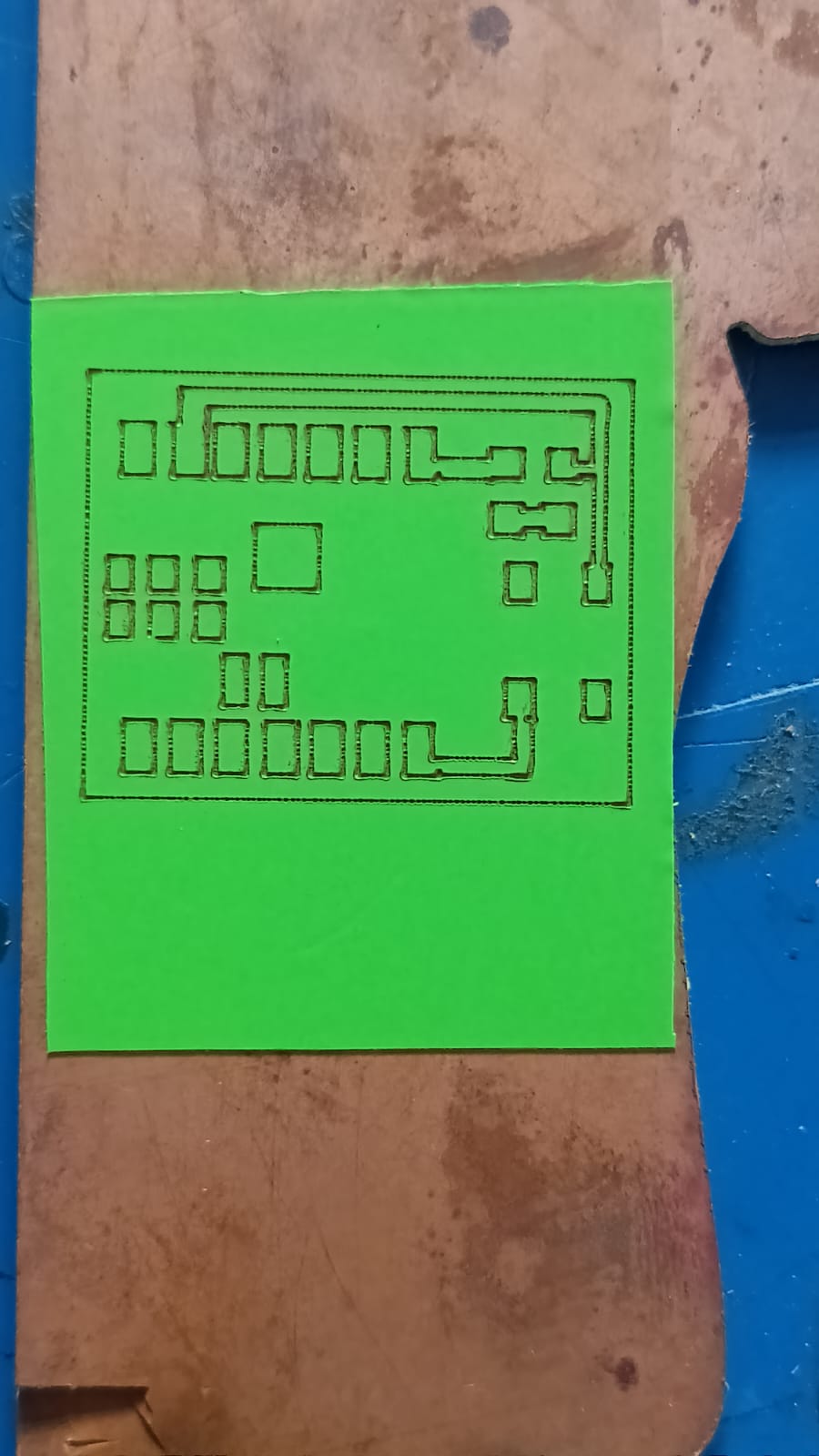
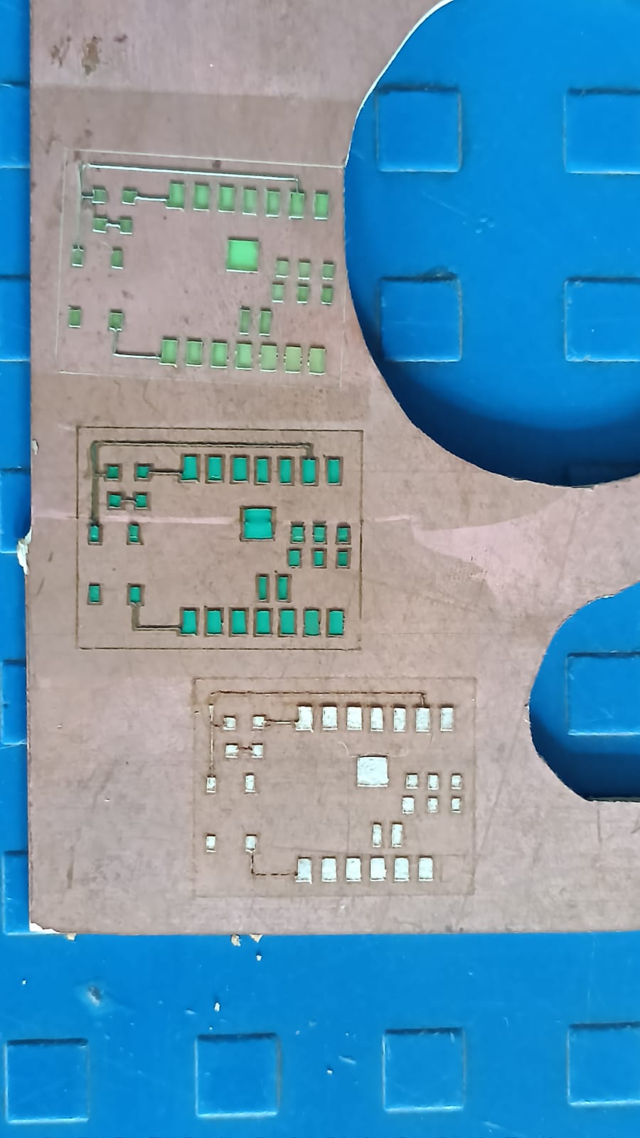
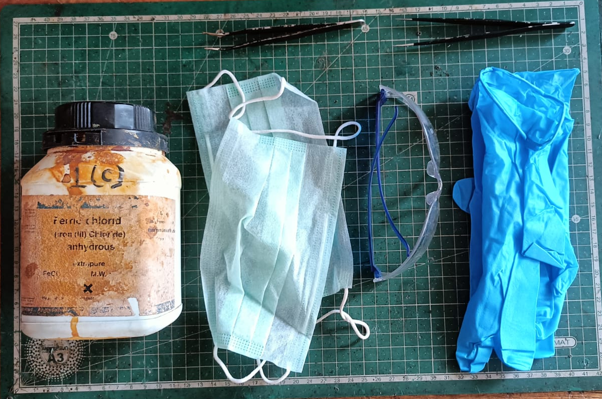
The next step was the chemical etching process. For this step, we followed proper safety precautions because chemicals were involved. We used ferric chloride solution mixed with distilled water to remove the unwanted copper from the board.
We also used the required tools like gloves, a container, and safety glasses during the process.
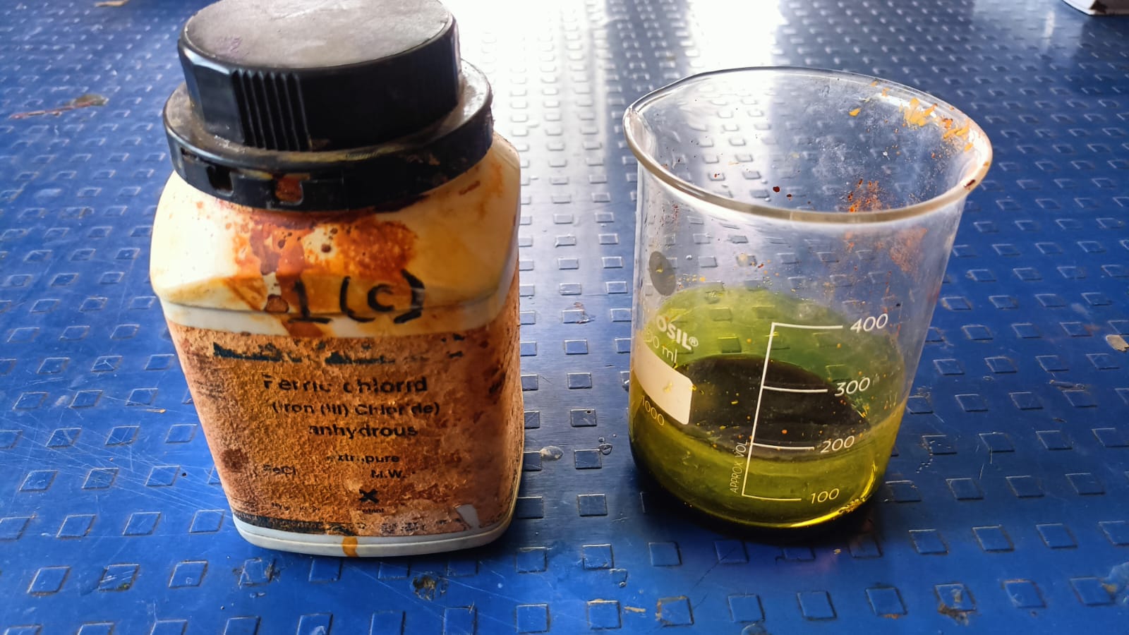
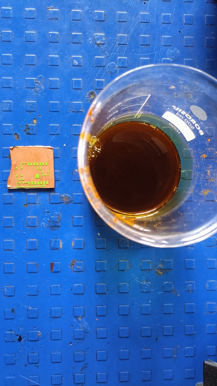
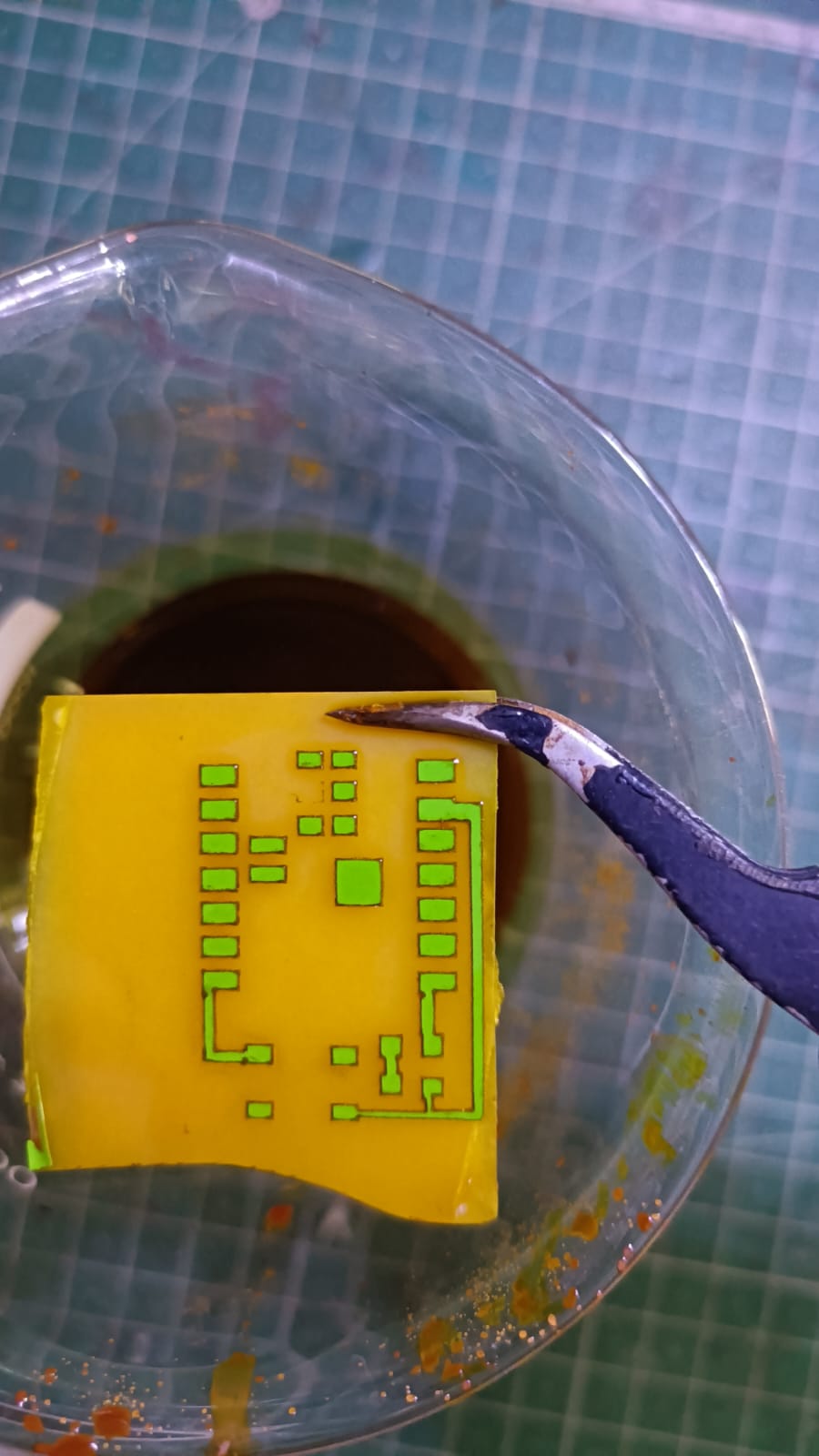
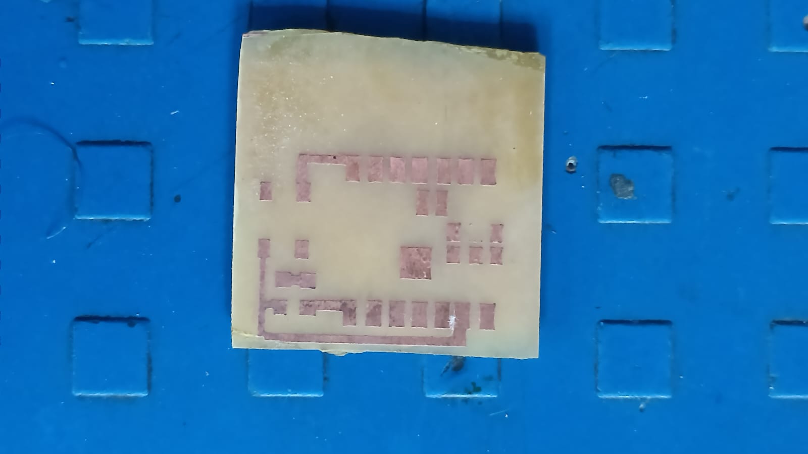
This step helped us achieve the final PCB traces on the copper plate.
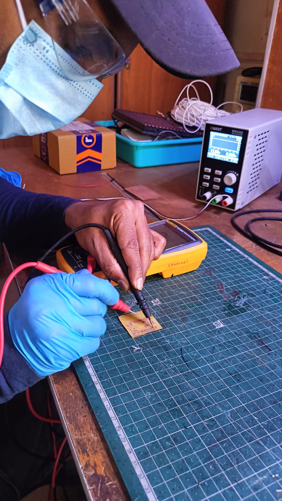
Before soldering, I checked all the PCB traces using a multimeter to ensure there were no short circuits or broken connections.
After confirming everything was correct, I soldered one push button, a 1k resistor, and a red LED according to the circuit design. Once soldering was completed, the board was tested and worked successfully.
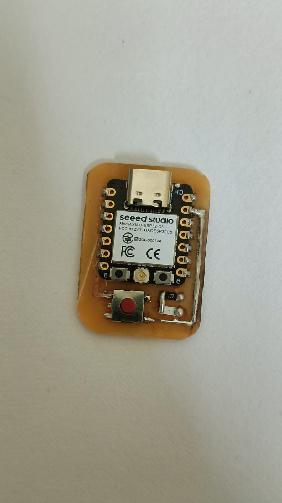
In the next step, I tested the LED using Arduino IDE. I wrote and uploaded a program to control the LED with the push button.
After connecting the board properly, I checked whether the LED turned ON and OFF when the button was pressed. The test was successful, and the circuit worked as expected.